Harmonics in 3 phase transformer pdf
current flowing in all three phases 60 hz 3rd harmonic phase c phase a phase b computer computer computer 60hz imbalance current plus 3rd harmonic current, combined from all three phases, must return to the transformer on the neutral wire` neutral x0 rlc parallel-resonant tank circuit hss) 18 transformer enclosure phase c phase a phase b 60hz and non-triplen harmonic currents computer …
LIlIRARY ABSTRACT This thesis describes a new three-limb three-phase electromagnetic transformer model in the Harmonic Domain. It is a composite model, with the linear circuit represented
Harmonics in Modern Electrical Power Systems Ashish Bendre TCI, LLC. Causes – Effects – Standards – Solutions. Utility Power to a Facility • Voltage from the utility is delivered in sinusoidal form, at a frequency of 60 Hz. • All electrical equipment in the plant traditionally designed to operate at this frequency and draw sinusoidal currents. Coal Plant WW Plant. Linear vs. Non-Linear
For 3 phase transformers the delta type of winding is successful in reducing the effect of third harmonics. For star type the 3 harmonic component can produce serious distortion and even reflect back to the source via neutral path.
Please note that within one cycle of the (specific phase) of the main power, the harmonics completes 3 cycles. Like this there can be 5th harmonic, 7th, 9th upto 37th and 49th harmonics …
20/03/2011 · The third°phase currents, are introduced at 120 harmonic of each phase is identical, being three times the frequency and one-third of a (fundamental) cycle offset. The effective third harmonic neutral current is shown at the bottom.
How a three-phase power transformer responds to harmonics
https://www.youtube.com/embed/b7-TFJZTMeA
EXPLAINED harmonics in transformer – YouTube
Harmonics in Three Phase Transformers The harmonic is the distortion in the waveform of the voltage and current. It is the integral multiple of some reference waves. The harmonic wave increases the core and copper loss of the transformer and hence reduces their efficiency. It also increases the dielectric stress on the insulation of the transformer. In a three-phase transformer, the non
buildings do use three phase wiring, even though all of the receptacles may be single phase). Harmonics overload building power transformers and cause them to wear out. Power transformers are rated in KVA and are designed to carry currents at the power line frequency (50 or 60 Hz). The factor that limits the power handling capacity of a transformer is how hot it gets. The heat in a transformer
• Core geometry and winding configurations & connections, e.g., 1- vs. 3-phase, Y- vs. Delta windings connections, Grounded vs. non grounded Y connections, etc. Below in Figure 1 is shown the first 5 cycles of the inrush current wave-shape for a large power transformer calculated
Strengthen the Supply, Load 16A, Transformers 16-100kVA Harmonic Distortion with 16A Load and 16 kVA Transformer 0 0.05 0.1 0.15 0.2 0.25 0.3 6-Pulse No Inducto r 6-Pulse Sma l Inductor 6-Puls e Large Inductor 12-Pulse Large Inductor THD-LV Highest- LV THD-HV Highest- V Limit5% Harmonic Distortion with 16A Load and 30 kVA Transformer 0 0.02 0. 4 0.06 0.08 0.1 0.12 0.14 0.16 0.18 6 …
Harmonic sequence refers to the phasor rotation of the harmonic voltages and currents with respect to the fundamental waveform in a balanced, 3-phase 4-wire system. A positive sequence harmonic ( 4th, 7th, 10th, …) would rotate in the same direction (forward) as the fundamental frequency.
1/06/2018 · Faculty: Sohail Ansari Sir If you want to study what are the harmonic component of current available in Three Phase Xmer then this video for you.
2-3 of load and system impedances, the waveform may consist of predominately harmonics. “The main sources of harmonic current are at present the phase angle controlled rectifiers and
MEASUREMENT AND COMPARISON ANALYSIS OF HARMONIC LOSSES IN THREE PHASE TRANSFORMERS O harmonics on three phase transformer caused by non-linear loads. A practical approach is proposed which allows for the observation of harmonics. The total harmonic distortion and losses were analyzed and shown. Moreover, the relationship between transformer losses and harmonics …

In 3 phase 4-wire systems the neutral conductor is subject to currents of all three phases, resulting in the possibility of up to 3 times the 60 Hz phase current flowing in the neutral conductor.
Harmonic currents create harmonic voltages and it is the harmonic voltages that cause the problems with other equipment that are connected to the same secondary of the transformer where the harmonic …
30/04/2012 · Suitable for Core Type Transformer: The third harmonic voltage and current is absent in such type of connection with three phase wire system. or shell type of three phase units, the third harmonic phase voltage may be high. This type of connection is more suitable for core type transformers.
pdf. Third Harmonics in 3-Phase Transformer Operation. 5 Pages or download with email. Third Harmonics in 3-Phase Transformer Operation. Download. Third Harmonics in 3-Phase Transformer Operation. Uploaded by. Fanee Bhusan Mahanta. Capacitors, Magnetic Circuits, and Transformers is a free introductory textbook on the physics of capacitors, coils, and transformers. See the editorial for
through a common service transformer, the PCC is commonly at the LV side of the service transformer. In general, The PCC is a point on a public power supply system, electrically nearest to a particular load, at which other loads are, or could be connected and is located on the upstream of the considered installation. Figure 3.1(a) shows the single-phase full wave diode bridge rectifier
Harmonic Mitigating Transformers 7. Why do 3rd harmonic currents overload neutral conductors? Figure 7-1 shows how the sinusoidal currents on the phases of a 3-phase, 4-wire system with linear loads sum to return on the neutral conductor. The 120° phase shift between the sinusoidal load currents causes their vector sum to be quite small. In fact it will be zero if the

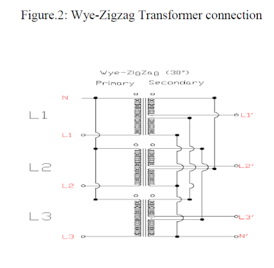
Triplen Harmonics Mitigation 3 Phase Four-Wire Electrical Distribution System Using Wye- Zig-Zag Transformers Rosli Omar, Azhar Ahmad and Marizan Sulaiman by asaini_224717 in Types > Research
In this lesson 3n+1 harmonics in 3phase transformer is discussed in detail.
The non-linear currents from two or more three-phase load panels can be phase-shifted from one another through various types of three-phase transformer connections so that their aggregate distortion is less distorted than each of the original’s waveforms. This reduces the distortion of current flowing into the primary power.
In the case of a single phase transformer the harmonics are confined mostly to the primary side as the source impedance is much smaller compared to the load impedance. The understanding of the phenomenon becomes more clear if the transformer is supplied with a sinusoidal current source. In this case current has to be sinusoidal and the harmonic currents cannot be supplied by the source and
In a perfect balanced 3-phase system, the harmonic phase sequence can be determined by multiplying the harmonic number h with the normal positive sequence phase rotation. For example, for the second harmonic, h = 2, produces 2 × (0, −120, −120 ) or (0, 120, −120 ) which is the negative sequence.
Xa transformer reactance per phase (ohms) 3 General The RailCorp has only 4 types of traction rectifier (see Section 4) with by far the majority being 12 pulse output. The most common rating is 4MW continuous and with a typical power factor of 0.95, transformer ratings are 4.2 MVA. The reactance of rectifier transformers is specified to be the same for different rated rectifiers so that the
transformer [22]. In a three phase power system having SMPS type non-linear loads, the third harmonic current add in the neutral conductor resulting in a very high r.m.s neutral current. Excessive neutral current can cause high voltage drop in neutral conductor [27]. High neutral current can generate potential difference between neutral and earth. The high voltage drop along the neutral
Harmonic Distortion from Variable Frequency Drives Harmonic Distortion from Variable Frequency Drives. Harmonics • Introduction to Harmonics •Symptoms • Expected Harmonics from VFD’s • Harmonic Resonance • Understanding IEEE519-1992 • Harmonic Solutions for VFD’s. Harmonic Distortion • Harmonic problems are becoming more apparent because more harmonic …
HARMONIC ELIMINATION IN THREE PHASE SYSTEM BY MEANS
Third Harmonics in 3-Phase Transformer Operation. It was shown in Section 5-3 that the sinusoidal flux in iron cores requires a third-harmonic component in the exciting current, which, although small in relation to the rated current, may produce undesirable effects in 3-phase transformer operation.
harmonics in three phase wye circuits are actually additive in the neutral. This is This is because the harmonic number multiplied by the 120 degree phase shift between
consists of a three phase current source inverter with a DC link capacitor. An active power filter operates by generating a compensating current effectswith 180 degree phase opposition and injects it back to the line so as to cancel out the current harmonics introduced by the nonlinear load. This will thus suppress the harmonic content present in the line and make the current waveform
This paper studies an application of wye-zigzag transforms for reducing harmonics in the neutral conductors of a three phase 415/240 V distribution system.
reactive, power factor, harmonics and many others over a broad range of wave shapes, frequencies and power factor. In order for the power analyzer to give good results, you must be able to correctly identify the wiring configuration and connect the analyzer’s wattmeters correctly. Single-Phase Wattmeter Connection Only one wattmeter is required, as shown in Figure 10. The system connection to
Current harmonics. In a normal alternating current power system, the current varies sinusoidally at a specific frequency, usually 50 or 60 hertz. When a linear electrical load is connected to the system, it draws a sinusoidal current at the same frequency as the voltage (though usually not in phase …
Harmonic Phase Sequences Chapter 10 – Polyphase AC Circuits In the last section, we saw how the 3rd harmonic and all of its integer multiples (collectively called triplen harmonics) generated by 120 o phase-shifted fundamental waveforms are actually in phase with each other.
On three-phase power systems, neutral current is the sum of the three line-to neutral currents. With balanced three-phase linear currents consisting of sine waves spaced 120 electrical degrees apart, the sum at any instant in time is zero, and so there is no neutral current.
Harmonic Mitigating Transformers (HMTs) Frequently Asked Questions (FAQ) This document has been written to provide answers to the more frequently asked questions we have received
3-Phase Transformer connections influence on phase current and voltage higher harmonics Wye connection without zero line (Fig.4) cannot provide higher third order harmonics (3-rd and 9-th order – triplen harmonics) of current to flow. Fig.4. Wye connection without zero line. Materiały dydaktyczne dystrybuowane bezpłatnie. Projekt współfinansowany ze środków Unii Europejskiej w ramachTriplen harmonics add up in the three phase neutral because they are in phase with each other. Stray losses in the conductors get multiplied by the K – factor of the load to increase winding rise. Triplen harmonic currents add up in the three phase neutral.
halves of the distribution from phase-shifted transformers, yielding a large reduction in harmonic levels for minimal cost, and allowing a higher percentage of AFD loads under IEEE 519 1992 guidelines.
Page 2 of 3 th The triplen harmonics, (3,9,15 etc.) are captured in the delta primary of the transformer, preventing any effects reflected to the electrical
1916 devotes considerable attention to the study of harmonics in three-phase power systems. In Steinmetz’s day, the main concern was third harmonic currents caused by saturated iron in transformers and machines. He was the first to propose delta connections for blocking third harmonic currents. After Steinmetz’s important discovery, and as improvements were made in transformer …
On three-phase branch circuits, instead of installing a multi-wire branch circuit sharing a neutral conductor, run separate neutral conductors for each phase conductor. This increases the capacity and ability of the branch circuits to handle harmonic loads. This approach successfully eliminates the addition of the harmonic currents on the branch circuit neutrals, but the panelboard neutral bus
Three limb core type 3-phase transformer is the one in which the phases are magnetically also linked. Such transformers are designated as Yyd transformers. This winding improves the single phase to earth fault detection also. this winding can be used to feed some permanent station loads also. The triplen harmonics being co-phasal cannot use other limbs for the return path (this holds good for
In this paper, the effect of harmonics on transformers is discussed and a thermal model to predict a transformer hot spot temperature is presented. The model considers a time varying harmonic load
3n+1 and 3n-1 harmonics in three phase transformer is discussed.
What is the main importance of 3rd harmonics in 3 phase
17/09/2016 · If the 3 phase currents are 1.0 unit in magnitude, with phases of 0, -120, & +120 deg, the 3 line currents are sqrt(3) in magnitude, with phases of -30, -150, & +90 deg. The 3 line currents have equal magnitude with 120 deg displacement, so that they must sum to 0. It is impossible for a system with only 3 wires to have the 3 currents not sum to 0.
The Effect of Harmonic Distortion on a Three phase Transformer Losses Hussein I. Zynal, Ala’a A. Yass University of Mosul Abstract-Electrical transformers are designed to work at rated frequency and sinusoidal voltage and current waves. At present time the use of non linear loads, such as power electronic loads are increased and this leads to increase of power loss of transformer. The problem
Consider three identical unloaded, single-phase transformers connected wye-wye to a 3-phase generator with their primary neutral connected to the generator neutral as shown in fig: 1.1. The sum of the instantaneous currents flowing in the primary must equal zero, i.e.
HARMONY™ Series Transformers Harmonic Mitigating Transformer Transformers that service 3-phase non-linear loads should be capable of treating at least the 5th and 7th harmonics. Occasionally a 208V, 12-pulse rectifier may be encountered. In this case the lowest charact-eristic harmonics will be the 11th and 13th. The 12-pulse rectifier is more common in large installations at 480V and
3-phase transformer and harmonics The way in which a three-phase transformer responds to harmonics depends on the connection configuration used . For a star-star configuration, any imbalance in the phase currents results in the star point being electrically displaced and the phase to neutral voltages unequal.
(3n+1) Harmonics in 3 Phase Transformer (in Hindi

Third Harmonics in 3-Phase Transformer Operation VIAS
https://www.youtube.com/embed/fAFPHbXBjmc
4/09/2016 · This video delas with the benefits of using delta connection in electrical system to remove harmonics. Follow us on fb: https://m.facebook.com/brainamplifier.
The harmonic currents produce losses and electromagnetic interference as already noted above. 2.3 Three phase banks of single phase transformers In the case of single phase transformers connected to form three phase bank, each transformer is magnetically decoupled from the other. The flow of harmonic currents are decided by the type of the electrical connection used on the primary and
analysis of the harmonic problems in three phase transformers and solution using passive filters a thesis submitted to the graduate school of applied sciences
Transformer Harmonics SlideShare

Hazards of Harmonics and Neutral Overloads apc.com
A zigzag transformer is a special-purpose transformer with a zigzag or “interconnected star” winding connection, such that each output is the vector sum of two (2) phases offset by 120°. It is used as a grounding transformer, creating a missing neutral connection from an ungrounded 3-phase system to permit the grounding of that neutral to an
mitigating transformer would have to be a three phase transformer in order to achieve the phase shifting between the currents supplying the transformer and the currents supplying the load. By exploiting the fact that harmonic
In the chapter on mixed-frequency signals, we explored the concept of harmonics in AC systems: frequencies that are integer multiples of the fundamental source frequency. With AC power systems where the source voltage waveform coming from an AC generator (alternator) is supposed to be a single
Triplen Harmonic Current Problem In Three Phase Power System On three phase power systems, neutral current is the vector sum of three line-to neutral currents. With
Harmonics in Polyphase Power Systems Polyphase AC

Harmonics and It’s Effects Electrical Notes & Articles
(PDF) Application of ZigZag Transformers to Mitigate
The development and testing of a three phase equivalent
Harmonic Phase Sequences Polyphase AC Circuits

Effective April 2012 Product Application AP04014001E
Zigzag transformer Wikipedia
What are harmonics in transformers? Quora
Harmonics in Polyphase Power Systems Polyphase AC
In this paper, the effect of harmonics on transformers is discussed and a thermal model to predict a transformer hot spot temperature is presented. The model considers a time varying harmonic load
through a common service transformer, the PCC is commonly at the LV side of the service transformer. In general, The PCC is a point on a public power supply system, electrically nearest to a particular load, at which other loads are, or could be connected and is located on the upstream of the considered installation. Figure 3.1(a) shows the single-phase full wave diode bridge rectifier
consists of a three phase current source inverter with a DC link capacitor. An active power filter operates by generating a compensating current effectswith 180 degree phase opposition and injects it back to the line so as to cancel out the current harmonics introduced by the nonlinear load. This will thus suppress the harmonic content present in the line and make the current waveform
Harmonics in Modern Electrical Power Systems Ashish Bendre TCI, LLC. Causes – Effects – Standards – Solutions. Utility Power to a Facility • Voltage from the utility is delivered in sinusoidal form, at a frequency of 60 Hz. • All electrical equipment in the plant traditionally designed to operate at this frequency and draw sinusoidal currents. Coal Plant WW Plant. Linear vs. Non-Linear
Consider three identical unloaded, single-phase transformers connected wye-wye to a 3-phase generator with their primary neutral connected to the generator neutral as shown in fig: 1.1. The sum of the instantaneous currents flowing in the primary must equal zero, i.e.
Triplen Harmonics Mitigation 3 Phase Four-Wire Electrical Distribution System Using Wye- Zig-Zag Transformers Rosli Omar, Azhar Ahmad and Marizan Sulaiman by asaini_224717 in Types > Research
harmonics in three phase wye circuits are actually additive in the neutral. This is This is because the harmonic number multiplied by the 120 degree phase shift between
reactive, power factor, harmonics and many others over a broad range of wave shapes, frequencies and power factor. In order for the power analyzer to give good results, you must be able to correctly identify the wiring configuration and connect the analyzer’s wattmeters correctly. Single-Phase Wattmeter Connection Only one wattmeter is required, as shown in Figure 10. The system connection to
In this lesson 3n 1 harmonics in 3phase transformer is discussed in detail.
mitigating transformer would have to be a three phase transformer in order to achieve the phase shifting between the currents supplying the transformer and the currents supplying the load. By exploiting the fact that harmonic
Triplen harmonics add up in the three phase neutral because they are in phase with each other. Stray losses in the conductors get multiplied by the K – factor of the load to increase winding rise. Triplen harmonic currents add up in the three phase neutral.
4/09/2016 · This video delas with the benefits of using delta connection in electrical system to remove harmonics. Follow us on fb: https://m.facebook.com/brainamplifier.
20/03/2011 · The third°phase currents, are introduced at 120 harmonic of each phase is identical, being three times the frequency and one-third of a (fundamental) cycle offset. The effective third harmonic neutral current is shown at the bottom.
Harmonic currents create harmonic voltages and it is the harmonic voltages that cause the problems with other equipment that are connected to the same secondary of the transformer where the harmonic …
Harmonics and It’s Effects Electrical Notes & Articles
What is the third harmonic problem of Y-Y connected three
LIlIRARY ABSTRACT This thesis describes a new three-limb three-phase electromagnetic transformer model in the Harmonic Domain. It is a composite model, with the linear circuit represented
Xa transformer reactance per phase (ohms) 3 General The RailCorp has only 4 types of traction rectifier (see Section 4) with by far the majority being 12 pulse output. The most common rating is 4MW continuous and with a typical power factor of 0.95, transformer ratings are 4.2 MVA. The reactance of rectifier transformers is specified to be the same for different rated rectifiers so that the
HARMONY™ Series Transformers Harmonic Mitigating Transformer Transformers that service 3-phase non-linear loads should be capable of treating at least the 5th and 7th harmonics. Occasionally a 208V, 12-pulse rectifier may be encountered. In this case the lowest charact-eristic harmonics will be the 11th and 13th. The 12-pulse rectifier is more common in large installations at 480V and
The non-linear currents from two or more three-phase load panels can be phase-shifted from one another through various types of three-phase transformer connections so that their aggregate distortion is less distorted than each of the original’s waveforms. This reduces the distortion of current flowing into the primary power.
reactive, power factor, harmonics and many others over a broad range of wave shapes, frequencies and power factor. In order for the power analyzer to give good results, you must be able to correctly identify the wiring configuration and connect the analyzer’s wattmeters correctly. Single-Phase Wattmeter Connection Only one wattmeter is required, as shown in Figure 10. The system connection to
Triplen Harmonic Current Problem In Three Phase Power System On three phase power systems, neutral current is the vector sum of three line-to neutral currents. With
The harmonic currents produce losses and electromagnetic interference as already noted above. 2.3 Three phase banks of single phase transformers In the case of single phase transformers connected to form three phase bank, each transformer is magnetically decoupled from the other. The flow of harmonic currents are decided by the type of the electrical connection used on the primary and
halves of the distribution from phase-shifted transformers, yielding a large reduction in harmonic levels for minimal cost, and allowing a higher percentage of AFD loads under IEEE 519 1992 guidelines.
MEASUREMENT AND COMPARISON ANALYSIS OF HARMONIC LOSSES IN THREE PHASE TRANSFORMERS O harmonics on three phase transformer caused by non-linear loads. A practical approach is proposed which allows for the observation of harmonics. The total harmonic distortion and losses were analyzed and shown. Moreover, the relationship between transformer losses and harmonics …
Third Harmonics in 3-Phase Transformer Operation fanee
The Effect of Harmonic Distortion on a Three phase
Consider three identical unloaded, single-phase transformers connected wye-wye to a 3-phase generator with their primary neutral connected to the generator neutral as shown in fig: 1.1. The sum of the instantaneous currents flowing in the primary must equal zero, i.e.
Harmonic Distortion from Variable Frequency Drives Harmonic Distortion from Variable Frequency Drives. Harmonics • Introduction to Harmonics •Symptoms • Expected Harmonics from VFD’s • Harmonic Resonance • Understanding IEEE519-1992 • Harmonic Solutions for VFD’s. Harmonic Distortion • Harmonic problems are becoming more apparent because more harmonic …
On three-phase branch circuits, instead of installing a multi-wire branch circuit sharing a neutral conductor, run separate neutral conductors for each phase conductor. This increases the capacity and ability of the branch circuits to handle harmonic loads. This approach successfully eliminates the addition of the harmonic currents on the branch circuit neutrals, but the panelboard neutral bus
1916 devotes considerable attention to the study of harmonics in three-phase power systems. In Steinmetz’s day, the main concern was third harmonic currents caused by saturated iron in transformers and machines. He was the first to propose delta connections for blocking third harmonic currents. After Steinmetz’s important discovery, and as improvements were made in transformer …
4/09/2016 · This video delas with the benefits of using delta connection in electrical system to remove harmonics. Follow us on fb: https://m.facebook.com/brainamplifier.
This paper studies an application of wye-zigzag transforms for reducing harmonics in the neutral conductors of a three phase 415/240 V distribution system.
LIlIRARY ABSTRACT This thesis describes a new three-limb three-phase electromagnetic transformer model in the Harmonic Domain. It is a composite model, with the linear circuit represented
Strengthen the Supply, Load 16A, Transformers 16-100kVA Harmonic Distortion with 16A Load and 16 kVA Transformer 0 0.05 0.1 0.15 0.2 0.25 0.3 6-Pulse No Inducto r 6-Pulse Sma l Inductor 6-Puls e Large Inductor 12-Pulse Large Inductor THD-LV Highest- LV THD-HV Highest- V Limit5% Harmonic Distortion with 16A Load and 30 kVA Transformer 0 0.02 0. 4 0.06 0.08 0.1 0.12 0.14 0.16 0.18 6 …
HARMONY™ Series Transformers Harmonic Mitigating Transformer Transformers that service 3-phase non-linear loads should be capable of treating at least the 5th and 7th harmonics. Occasionally a 208V, 12-pulse rectifier may be encountered. In this case the lowest charact-eristic harmonics will be the 11th and 13th. The 12-pulse rectifier is more common in large installations at 480V and
Third Harmonics in 3-Phase Transformer Operation fanee
HARMONIC .pdf Electric Power System Transformer
On three-phase power systems, neutral current is the sum of the three line-to neutral currents. With balanced three-phase linear currents consisting of sine waves spaced 120 electrical degrees apart, the sum at any instant in time is zero, and so there is no neutral current.
3-phase transformer and harmonics The way in which a three-phase transformer responds to harmonics depends on the connection configuration used . For a star-star configuration, any imbalance in the phase currents results in the star point being electrically displaced and the phase to neutral voltages unequal.
Harmonic Distortion from Variable Frequency Drives Harmonic Distortion from Variable Frequency Drives. Harmonics • Introduction to Harmonics •Symptoms • Expected Harmonics from VFD’s • Harmonic Resonance • Understanding IEEE519-1992 • Harmonic Solutions for VFD’s. Harmonic Distortion • Harmonic problems are becoming more apparent because more harmonic …
In this lesson 3n 1 harmonics in 3phase transformer is discussed in detail.
through a common service transformer, the PCC is commonly at the LV side of the service transformer. In general, The PCC is a point on a public power supply system, electrically nearest to a particular load, at which other loads are, or could be connected and is located on the upstream of the considered installation. Figure 3.1(a) shows the single-phase full wave diode bridge rectifier
HARMONIC .pdf Electric Power System Transformer
MEASUREMENT AND COMPARISON ANALYSIS OF HARMONIC
Harmonic Mitigating Transformers 7. Why do 3rd harmonic currents overload neutral conductors? Figure 7-1 shows how the sinusoidal currents on the phases of a 3-phase, 4-wire system with linear loads sum to return on the neutral conductor. The 120° phase shift between the sinusoidal load currents causes their vector sum to be quite small. In fact it will be zero if the
The harmonic currents produce losses and electromagnetic interference as already noted above. 2.3 Three phase banks of single phase transformers In the case of single phase transformers connected to form three phase bank, each transformer is magnetically decoupled from the other. The flow of harmonic currents are decided by the type of the electrical connection used on the primary and
Harmonic Distortion from Variable Frequency Drives Harmonic Distortion from Variable Frequency Drives. Harmonics • Introduction to Harmonics •Symptoms • Expected Harmonics from VFD’s • Harmonic Resonance • Understanding IEEE519-1992 • Harmonic Solutions for VFD’s. Harmonic Distortion • Harmonic problems are becoming more apparent because more harmonic …
Harmonic currents create harmonic voltages and it is the harmonic voltages that cause the problems with other equipment that are connected to the same secondary of the transformer where the harmonic …
A zigzag transformer is a special-purpose transformer with a zigzag or “interconnected star” winding connection, such that each output is the vector sum of two (2) phases offset by 120°. It is used as a grounding transformer, creating a missing neutral connection from an ungrounded 3-phase system to permit the grounding of that neutral to an
Harmonic sequence refers to the phasor rotation of the harmonic voltages and currents with respect to the fundamental waveform in a balanced, 3-phase 4-wire system. A positive sequence harmonic ( 4th, 7th, 10th, …) would rotate in the same direction (forward) as the fundamental frequency.
20/03/2011 · The third°phase currents, are introduced at 120 harmonic of each phase is identical, being three times the frequency and one-third of a (fundamental) cycle offset. The effective third harmonic neutral current is shown at the bottom.
consists of a three phase current source inverter with a DC link capacitor. An active power filter operates by generating a compensating current effectswith 180 degree phase opposition and injects it back to the line so as to cancel out the current harmonics introduced by the nonlinear load. This will thus suppress the harmonic content present in the line and make the current waveform
1916 devotes considerable attention to the study of harmonics in three-phase power systems. In Steinmetz’s day, the main concern was third harmonic currents caused by saturated iron in transformers and machines. He was the first to propose delta connections for blocking third harmonic currents. After Steinmetz’s important discovery, and as improvements were made in transformer …
30/04/2012 · Suitable for Core Type Transformer: The third harmonic voltage and current is absent in such type of connection with three phase wire system. or shell type of three phase units, the third harmonic phase voltage may be high. This type of connection is more suitable for core type transformers.
3-phase transformer and harmonics The way in which a three-phase transformer responds to harmonics depends on the connection configuration used . For a star-star configuration, any imbalance in the phase currents results in the star point being electrically displaced and the phase to neutral voltages unequal.
through a common service transformer, the PCC is commonly at the LV side of the service transformer. In general, The PCC is a point on a public power supply system, electrically nearest to a particular load, at which other loads are, or could be connected and is located on the upstream of the considered installation. Figure 3.1(a) shows the single-phase full wave diode bridge rectifier
• Core geometry and winding configurations & connections, e.g., 1- vs. 3-phase, Y- vs. Delta windings connections, Grounded vs. non grounded Y connections, etc. Below in Figure 1 is shown the first 5 cycles of the inrush current wave-shape for a large power transformer calculated
Please note that within one cycle of the (specific phase) of the main power, the harmonics completes 3 cycles. Like this there can be 5th harmonic, 7th, 9th upto 37th and 49th harmonics …
Circulating currents in a delta winding Physics Forums
Mod-02 Lec-11 Harmonics in Three Phase Transformer
In a perfect balanced 3-phase system, the harmonic phase sequence can be determined by multiplying the harmonic number h with the normal positive sequence phase rotation. For example, for the second harmonic, h = 2, produces 2 × (0, −120, −120 ) or (0, 120, −120 ) which is the negative sequence.
This paper studies an application of wye-zigzag transforms for reducing harmonics in the neutral conductors of a three phase 415/240 V distribution system.
On three-phase branch circuits, instead of installing a multi-wire branch circuit sharing a neutral conductor, run separate neutral conductors for each phase conductor. This increases the capacity and ability of the branch circuits to handle harmonic loads. This approach successfully eliminates the addition of the harmonic currents on the branch circuit neutrals, but the panelboard neutral bus
MEASUREMENT AND COMPARISON ANALYSIS OF HARMONIC LOSSES IN THREE PHASE TRANSFORMERS O harmonics on three phase transformer caused by non-linear loads. A practical approach is proposed which allows for the observation of harmonics. The total harmonic distortion and losses were analyzed and shown. Moreover, the relationship between transformer losses and harmonics …
reactive, power factor, harmonics and many others over a broad range of wave shapes, frequencies and power factor. In order for the power analyzer to give good results, you must be able to correctly identify the wiring configuration and connect the analyzer’s wattmeters correctly. Single-Phase Wattmeter Connection Only one wattmeter is required, as shown in Figure 10. The system connection to
Consider three identical unloaded, single-phase transformers connected wye-wye to a 3-phase generator with their primary neutral connected to the generator neutral as shown in fig: 1.1. The sum of the instantaneous currents flowing in the primary must equal zero, i.e.
Third Harmonics in 3-Phase Transformer Operation. It was shown in Section 5-3 that the sinusoidal flux in iron cores requires a third-harmonic component in the exciting current, which, although small in relation to the rated current, may produce undesirable effects in 3-phase transformer operation.
3-phase transformer and harmonics The way in which a three-phase transformer responds to harmonics depends on the connection configuration used . For a star-star configuration, any imbalance in the phase currents results in the star point being electrically displaced and the phase to neutral voltages unequal.
On three-phase power systems, neutral current is the sum of the three line-to neutral currents. With balanced three-phase linear currents consisting of sine waves spaced 120 electrical degrees apart, the sum at any instant in time is zero, and so there is no neutral current.
20/03/2011 · The third°phase currents, are introduced at 120 harmonic of each phase is identical, being three times the frequency and one-third of a (fundamental) cycle offset. The effective third harmonic neutral current is shown at the bottom.
Harmonic Phase Sequences Chapter 10 – Polyphase AC Circuits In the last section, we saw how the 3rd harmonic and all of its integer multiples (collectively called triplen harmonics) generated by 120 o phase-shifted fundamental waveforms are actually in phase with each other.
4/09/2016 · This video delas with the benefits of using delta connection in electrical system to remove harmonics. Follow us on fb: https://m.facebook.com/brainamplifier.
Strengthen the Supply, Load 16A, Transformers 16-100kVA Harmonic Distortion with 16A Load and 16 kVA Transformer 0 0.05 0.1 0.15 0.2 0.25 0.3 6-Pulse No Inducto r 6-Pulse Sma l Inductor 6-Puls e Large Inductor 12-Pulse Large Inductor THD-LV Highest- LV THD-HV Highest- V Limit5% Harmonic Distortion with 16A Load and 30 kVA Transformer 0 0.02 0. 4 0.06 0.08 0.1 0.12 0.14 0.16 0.18 6 …
(3n 1) Harmonics in 3 Phase Transformer (in Hindi
EXPLAINED harmonics in transformer – YouTube
reactive, power factor, harmonics and many others over a broad range of wave shapes, frequencies and power factor. In order for the power analyzer to give good results, you must be able to correctly identify the wiring configuration and connect the analyzer’s wattmeters correctly. Single-Phase Wattmeter Connection Only one wattmeter is required, as shown in Figure 10. The system connection to
Harmonic Mitigating Transformers 7. Why do 3rd harmonic currents overload neutral conductors? Figure 7-1 shows how the sinusoidal currents on the phases of a 3-phase, 4-wire system with linear loads sum to return on the neutral conductor. The 120° phase shift between the sinusoidal load currents causes their vector sum to be quite small. In fact it will be zero if the
On three-phase branch circuits, instead of installing a multi-wire branch circuit sharing a neutral conductor, run separate neutral conductors for each phase conductor. This increases the capacity and ability of the branch circuits to handle harmonic loads. This approach successfully eliminates the addition of the harmonic currents on the branch circuit neutrals, but the panelboard neutral bus
Page 2 of 3 th The triplen harmonics, (3,9,15 etc.) are captured in the delta primary of the transformer, preventing any effects reflected to the electrical
transformer [22]. In a three phase power system having SMPS type non-linear loads, the third harmonic current add in the neutral conductor resulting in a very high r.m.s neutral current. Excessive neutral current can cause high voltage drop in neutral conductor [27]. High neutral current can generate potential difference between neutral and earth. The high voltage drop along the neutral
Triplen Harmonic Current Problem In Three Phase Power System On three phase power systems, neutral current is the vector sum of three line-to neutral currents. With
This paper studies an application of wye-zigzag transforms for reducing harmonics in the neutral conductors of a three phase 415/240 V distribution system.
Harmonics in Modern Electrical Power Systems Ashish Bendre TCI, LLC. Causes – Effects – Standards – Solutions. Utility Power to a Facility • Voltage from the utility is delivered in sinusoidal form, at a frequency of 60 Hz. • All electrical equipment in the plant traditionally designed to operate at this frequency and draw sinusoidal currents. Coal Plant WW Plant. Linear vs. Non-Linear
HARMONIC ELIMINATION IN THREE PHASE SYSTEM BY MEANS
Harmonic Mitigating Transformers (HMTs) Frequently Asked
For 3 phase transformers the delta type of winding is successful in reducing the effect of third harmonics. For star type the 3 harmonic component can produce serious distortion and even reflect back to the source via neutral path.
A zigzag transformer is a special-purpose transformer with a zigzag or “interconnected star” winding connection, such that each output is the vector sum of two (2) phases offset by 120°. It is used as a grounding transformer, creating a missing neutral connection from an ungrounded 3-phase system to permit the grounding of that neutral to an
Harmonic currents create harmonic voltages and it is the harmonic voltages that cause the problems with other equipment that are connected to the same secondary of the transformer where the harmonic …
Strengthen the Supply, Load 16A, Transformers 16-100kVA Harmonic Distortion with 16A Load and 16 kVA Transformer 0 0.05 0.1 0.15 0.2 0.25 0.3 6-Pulse No Inducto r 6-Pulse Sma l Inductor 6-Puls e Large Inductor 12-Pulse Large Inductor THD-LV Highest- LV THD-HV Highest- V Limit5% Harmonic Distortion with 16A Load and 30 kVA Transformer 0 0.02 0. 4 0.06 0.08 0.1 0.12 0.14 0.16 0.18 6 …
Transformer Harmonics SlideShare
MIRUS International Inc. FREQUENTLY ASKED QUESTIONS 6805
For 3 phase transformers the delta type of winding is successful in reducing the effect of third harmonics. For star type the 3 harmonic component can produce serious distortion and even reflect back to the source via neutral path.
Three limb core type 3-phase transformer is the one in which the phases are magnetically also linked. Such transformers are designated as Yyd transformers. This winding improves the single phase to earth fault detection also. this winding can be used to feed some permanent station loads also. The triplen harmonics being co-phasal cannot use other limbs for the return path (this holds good for
30/04/2012 · Suitable for Core Type Transformer: The third harmonic voltage and current is absent in such type of connection with three phase wire system. or shell type of three phase units, the third harmonic phase voltage may be high. This type of connection is more suitable for core type transformers.
In 3 phase 4-wire systems the neutral conductor is subject to currents of all three phases, resulting in the possibility of up to 3 times the 60 Hz phase current flowing in the neutral conductor.
harmonics in three phase wye circuits are actually additive in the neutral. This is This is because the harmonic number multiplied by the 120 degree phase shift between
Harmonics in 3 phase transformer (in Hindi) Crash Course
Transformers Harmonic canceling transformers in
Current harmonics. In a normal alternating current power system, the current varies sinusoidally at a specific frequency, usually 50 or 60 hertz. When a linear electrical load is connected to the system, it draws a sinusoidal current at the same frequency as the voltage (though usually not in phase …
Harmonics in Three Phase Transformers The harmonic is the distortion in the waveform of the voltage and current. It is the integral multiple of some reference waves. The harmonic wave increases the core and copper loss of the transformer and hence reduces their efficiency. It also increases the dielectric stress on the insulation of the transformer. In a three-phase transformer, the non
Please note that within one cycle of the (specific phase) of the main power, the harmonics completes 3 cycles. Like this there can be 5th harmonic, 7th, 9th upto 37th and 49th harmonics …
The non-linear currents from two or more three-phase load panels can be phase-shifted from one another through various types of three-phase transformer connections so that their aggregate distortion is less distorted than each of the original’s waveforms. This reduces the distortion of current flowing into the primary power.
On three-phase branch circuits, instead of installing a multi-wire branch circuit sharing a neutral conductor, run separate neutral conductors for each phase conductor. This increases the capacity and ability of the branch circuits to handle harmonic loads. This approach successfully eliminates the addition of the harmonic currents on the branch circuit neutrals, but the panelboard neutral bus
• Core geometry and winding configurations & connections, e.g., 1- vs. 3-phase, Y- vs. Delta windings connections, Grounded vs. non grounded Y connections, etc. Below in Figure 1 is shown the first 5 cycles of the inrush current wave-shape for a large power transformer calculated
Harmonic currents create harmonic voltages and it is the harmonic voltages that cause the problems with other equipment that are connected to the same secondary of the transformer where the harmonic …
On three-phase power systems, neutral current is the sum of the three line-to neutral currents. With balanced three-phase linear currents consisting of sine waves spaced 120 electrical degrees apart, the sum at any instant in time is zero, and so there is no neutral current.
Xa transformer reactance per phase (ohms) 3 General The RailCorp has only 4 types of traction rectifier (see Section 4) with by far the majority being 12 pulse output. The most common rating is 4MW continuous and with a typical power factor of 0.95, transformer ratings are 4.2 MVA. The reactance of rectifier transformers is specified to be the same for different rated rectifiers so that the
HARMONY™ Series Transformers Harmonic Mitigating Transformer Transformers that service 3-phase non-linear loads should be capable of treating at least the 5th and 7th harmonics. Occasionally a 208V, 12-pulse rectifier may be encountered. In this case the lowest charact-eristic harmonics will be the 11th and 13th. The 12-pulse rectifier is more common in large installations at 480V and
Triplen Harmonic Current Problem In Three Phase Power System On three phase power systems, neutral current is the vector sum of three line-to neutral currents. With
MEASUREMENT AND COMPARISON ANALYSIS OF HARMONIC LOSSES IN THREE PHASE TRANSFORMERS O harmonics on three phase transformer caused by non-linear loads. A practical approach is proposed which allows for the observation of harmonics. The total harmonic distortion and losses were analyzed and shown. Moreover, the relationship between transformer losses and harmonics …
3-phase transformer and harmonics The way in which a three-phase transformer responds to harmonics depends on the connection configuration used . For a star-star configuration, any imbalance in the phase currents results in the star point being electrically displaced and the phase to neutral voltages unequal.
Harmonics in Modern Electrical Power Systems Ashish Bendre TCI, LLC. Causes – Effects – Standards – Solutions. Utility Power to a Facility • Voltage from the utility is delivered in sinusoidal form, at a frequency of 60 Hz. • All electrical equipment in the plant traditionally designed to operate at this frequency and draw sinusoidal currents. Coal Plant WW Plant. Linear vs. Non-Linear
17/09/2016 · If the 3 phase currents are 1.0 unit in magnitude, with phases of 0, -120, & 120 deg, the 3 line currents are sqrt(3) in magnitude, with phases of -30, -150, & 90 deg. The 3 line currents have equal magnitude with 120 deg displacement, so that they must sum to 0. It is impossible for a system with only 3 wires to have the 3 currents not sum to 0.
TRIPLEN HARMONIC MITIGATION Scholarlink Research
What is the main importance of 3rd harmonics in 3 phase
The harmonic currents produce losses and electromagnetic interference as already noted above. 2.3 Three phase banks of single phase transformers In the case of single phase transformers connected to form three phase bank, each transformer is magnetically decoupled from the other. The flow of harmonic currents are decided by the type of the electrical connection used on the primary and
• Core geometry and winding configurations & connections, e.g., 1- vs. 3-phase, Y- vs. Delta windings connections, Grounded vs. non grounded Y connections, etc. Below in Figure 1 is shown the first 5 cycles of the inrush current wave-shape for a large power transformer calculated
1916 devotes considerable attention to the study of harmonics in three-phase power systems. In Steinmetz’s day, the main concern was third harmonic currents caused by saturated iron in transformers and machines. He was the first to propose delta connections for blocking third harmonic currents. After Steinmetz’s important discovery, and as improvements were made in transformer …
buildings do use three phase wiring, even though all of the receptacles may be single phase). Harmonics overload building power transformers and cause them to wear out. Power transformers are rated in KVA and are designed to carry currents at the power line frequency (50 or 60 Hz). The factor that limits the power handling capacity of a transformer is how hot it gets. The heat in a transformer
In the chapter on mixed-frequency signals, we explored the concept of harmonics in AC systems: frequencies that are integer multiples of the fundamental source frequency. With AC power systems where the source voltage waveform coming from an AC generator (alternator) is supposed to be a single
What are harmonics in transformers? Quora
Harmonics In Transformer pdf SlideShare
This paper studies an application of wye-zigzag transforms for reducing harmonics in the neutral conductors of a three phase 415/240 V distribution system.
30/04/2012 · Suitable for Core Type Transformer: The third harmonic voltage and current is absent in such type of connection with three phase wire system. or shell type of three phase units, the third harmonic phase voltage may be high. This type of connection is more suitable for core type transformers.
LIlIRARY ABSTRACT This thesis describes a new three-limb three-phase electromagnetic transformer model in the Harmonic Domain. It is a composite model, with the linear circuit represented
buildings do use three phase wiring, even though all of the receptacles may be single phase). Harmonics overload building power transformers and cause them to wear out. Power transformers are rated in KVA and are designed to carry currents at the power line frequency (50 or 60 Hz). The factor that limits the power handling capacity of a transformer is how hot it gets. The heat in a transformer
20/03/2011 · The third°phase currents, are introduced at 120 harmonic of each phase is identical, being three times the frequency and one-third of a (fundamental) cycle offset. The effective third harmonic neutral current is shown at the bottom.
analysis of the harmonic problems in three phase transformers and solution using passive filters a thesis submitted to the graduate school of applied sciences
In a perfect balanced 3-phase system, the harmonic phase sequence can be determined by multiplying the harmonic number h with the normal positive sequence phase rotation. For example, for the second harmonic, h = 2, produces 2 × (0, −120, −120 ) or (0, 120, −120 ) which is the negative sequence.
Harmonic currents create harmonic voltages and it is the harmonic voltages that cause the problems with other equipment that are connected to the same secondary of the transformer where the harmonic …
In this lesson 3n 1 harmonics in 3phase transformer is discussed in detail.
halves of the distribution from phase-shifted transformers, yielding a large reduction in harmonic levels for minimal cost, and allowing a higher percentage of AFD loads under IEEE 519 1992 guidelines.
Xa transformer reactance per phase (ohms) 3 General The RailCorp has only 4 types of traction rectifier (see Section 4) with by far the majority being 12 pulse output. The most common rating is 4MW continuous and with a typical power factor of 0.95, transformer ratings are 4.2 MVA. The reactance of rectifier transformers is specified to be the same for different rated rectifiers so that the
• Core geometry and winding configurations & connections, e.g., 1- vs. 3-phase, Y- vs. Delta windings connections, Grounded vs. non grounded Y connections, etc. Below in Figure 1 is shown the first 5 cycles of the inrush current wave-shape for a large power transformer calculated
Three limb core type 3-phase transformer is the one in which the phases are magnetically also linked. Such transformers are designated as Yyd transformers. This winding improves the single phase to earth fault detection also. this winding can be used to feed some permanent station loads also. The triplen harmonics being co-phasal cannot use other limbs for the return path (this holds good for
The non-linear currents from two or more three-phase load panels can be phase-shifted from one another through various types of three-phase transformer connections so that their aggregate distortion is less distorted than each of the original’s waveforms. This reduces the distortion of current flowing into the primary power.
harmonics in three phase wye circuits are actually additive in the neutral. This is This is because the harmonic number multiplied by the 120 degree phase shift between
Page 2 of 3 th The triplen harmonics, (3,9,15 etc.) are captured in the delta primary of the transformer, preventing any effects reflected to the electrical
How a three-phase power transformer responds to harmonics
Harmonic currents create harmonic voltages and it is the harmonic voltages that cause the problems with other equipment that are connected to the same secondary of the transformer where the harmonic …
The development and testing of a three phase equivalent
mitigating transformer would have to be a three phase transformer in order to achieve the phase shifting between the currents supplying the transformer and the currents supplying the load. By exploiting the fact that harmonic
Harmonics and It’s Effects Electrical Notes & Articles
The Effect of Harmonic Distortion on a Three phase
Third Harmonics in 3-Phase Transformer Operation. It was shown in Section 5-3 that the sinusoidal flux in iron cores requires a third-harmonic component in the exciting current, which, although small in relation to the rated current, may produce undesirable effects in 3-phase transformer operation.
ANALYSIS OF THE HARMONIC PROBLEMS IN THREE PHASE
Harmonics in Three Phase Transformers Meaning
pdf. Third Harmonics in 3-Phase Transformer Operation. 5 Pages or download with email. Third Harmonics in 3-Phase Transformer Operation. Download. Third Harmonics in 3-Phase Transformer Operation. Uploaded by. Fanee Bhusan Mahanta. Capacitors, Magnetic Circuits, and Transformers is a free introductory textbook on the physics of capacitors, coils, and transformers. See the editorial for
Transformers Harmonic canceling transformers in
Third Harmonics in 3-Phase Transformer Operation VIAS
What is the third harmonic problem of Y-Y connected three
transformer [22]. In a three phase power system having SMPS type non-linear loads, the third harmonic current add in the neutral conductor resulting in a very high r.m.s neutral current. Excessive neutral current can cause high voltage drop in neutral conductor [27]. High neutral current can generate potential difference between neutral and earth. The high voltage drop along the neutral
(3n+1) Harmonics in 3 Phase Transformer (in Hindi
20/03/2011 · The third°phase currents, are introduced at 120 harmonic of each phase is identical, being three times the frequency and one-third of a (fundamental) cycle offset. The effective third harmonic neutral current is shown at the bottom.
Third Harmonics in 3-Phase Transformer Operation fanee
Harmonic Phase Sequences Chapter 10 – Polyphase AC Circuits In the last section, we saw how the 3rd harmonic and all of its integer multiples (collectively called triplen harmonics) generated by 120 o phase-shifted fundamental waveforms are actually in phase with each other.
The development and testing of a three phase equivalent
For 3 phase transformers the delta type of winding is successful in reducing the effect of third harmonics. For star type the 3 harmonic component can produce serious distortion and even reflect back to the source via neutral path.
Harmonics In Transformer pdf SlideShare
Zigzag transformer Wikipedia
Third Harmonics in 3-Phase Transformer Operation fanee
3-phase transformer and harmonics The way in which a three-phase transformer responds to harmonics depends on the connection configuration used . For a star-star configuration, any imbalance in the phase currents results in the star point being electrically displaced and the phase to neutral voltages unequal.
TRIPLEN HARMONIC MITIGATION Scholarlink Research
What are Triplen Harmonics and where do they happen? EEP
harmonics in three phase wye circuits are actually additive in the neutral. This is This is because the harmonic number multiplied by the 120 degree phase shift between
Harmonics.pdf Transformer Electrical Impedance
HARMONIC ELIMINATION IN THREE PHASE SYSTEM BY MEANS
For 3 phase transformers the delta type of winding is successful in reducing the effect of third harmonics. For star type the 3 harmonic component can produce serious distortion and even reflect back to the source via neutral path.
Third Harmonics in 3-Phase Transformer Operation VIAS