Crystal oscillator circuit design pdf
PARALLEL CIRCUIT:A parallel resonant oscillator circuit uses a crystal unit which is designed to operate with a specified value of load capacitance. This will result in a crystal frequency which is higher than the series resonant frequency but lower than the true parallel resonant frequency. These circuits do not provide paths other than through the crystal unit to complete the feedback loop
In the oscillator or VCXO design, the crystal model is required. A commonly adopted crystal resonator A commonly adopted crystal resonator model [1-2] is depicted as Figure 3 .
In this application note we shall discuss our recommended crystal oscillator circuit, explain each component in the circuit and provide some guidelines on selecting values for these components. Finally, we shall give a few precautions to take in
Technical notes 1 Circuit Design for Crystal Oscillator Peripheral Circuits Circuit Design Guide for Noise Reduction [Preface] During the design and layout of electronic devices and communications systems, careful consideration
Selection of the right crystal, correct load circuit, and proper board layout are important for a stable crystal oscillator. This application report summarizes crystal oscillator function and explains the …
6.2 Background 6-3 Figure 6.2: Crystal Equivalent Circuit Crystal Oscillator You can see that the previous circuit lacks precision. Another way to design
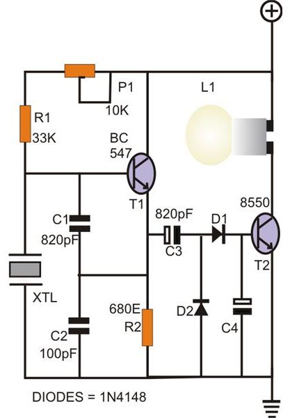
This circuit uses a 1 MHz crystal oscillator, which is often used to generate the clock frequencies for microprocessor circuits. 1 MHz is perfect for a simple AM transmitter circuit because 1 MHz falls right in the middle of the band that’s used for AM radio transmissions.
contained within the feedback loop of the oscillator circuit. If the application requires a “parallel” resonant crystal, the value of load capacitance must be specified. If the application requires a “series” resonant crystal, load capacitance is not a factor and need not be specified. Load capacitance is the amount of capacitance measured or computed across the crystal terminals on the PCB
A. Conventional Crystal Oscillator Circuit The conventional crystal oscillator circuit widely used in electronic system is based on structure of pierce.
Crystal oscillator : The oscillator circuit is normally a standard circuit, but one that is designed to give the operating operating conditions for the crystal with ideal drive levels, etc. Voltage regulator: In order to prevent external voltage changes from introducing unwanted frequency shifts, the overall TCXO should incorporate a voltage regulator which itself should not introduce unwanted
Oscillator Design •Introduction –What makes an oscillator? •Types of oscillators –Fixed frequency or voltage controlled oscillator –LC resonator –Ring Oscillator –Crystal resonator •Design of oscillators –Frequency control, stability –Amplitude limits –Buffered output –isolation –Bias circuits –Voltage control –Phase noise. 2 Oscillator Requirements •Power
the complexity of crystal oscillation circuit design and the difficulty of limiting jitter and phase noise. If If we can achieve high-frequency fundamental oscillation using crystal devices, it …
Circuit #2: The tuned amplifier can form the core of an oscillator. We need to add feedback and one more inversion. If (gm RP) 2 ≥ 1, this circuit will oscillate.
AP-155 INTRODUCTION Intel’s microcontroller families (MCS É-48, MCS -51, and iACX-96) contain a circuit that is commonly re-ferred to as the ‘‘on-chip oscillator’’.
cuits that make up an oscillator circuit. The product design engineer should also consult with the crystal man-ufacturer about the needs of their product design. OSCILLATOR MODELS There are several methods to modeling oscillator behavior. One form is known as the one port view or negative resistance model. It predicts the behavior of the oscillator as an active network generating an …
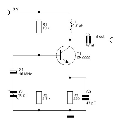
Power Supply Circuit Designer Colpitts 1MHz To 20 MHz Crysta l Os cilla tor Circuit This is a simple Colpitts crystal oscillator for 1 to 20 MHz, Amplifiers Battery Charger RF Schematics Measuring Circuits
Crystal Oscillator Design Wiley Encyclopedia of
https://www.youtube.com/embed/yYGwfVnGAdg
AN2606 Practical Considerations for Working With Low
A disadvantage of aperiodic oscillator circuits is the tendency to oscillate at the third or higher overtone of the crystal, or to a non-harmonic spurious resonance. In difficult cases, capacitance C2 should be replaced by a resonant circuit, which is detuned so that it is capacitive at the nominal frequency (principle of the Tritet oscillator).
32768 Hz oscillator circuit are the input and output cap acitance of the oscillator pins, EXTAL, and XTAL, respectively, and that the microcontroller has sufficient drive capability for the crystal…
AND8053/D Designing Crystal Oscillators with Modern CMOS Gates Prepared by: Fred Zlotnick Applications Manager INTRODUCTION Designing a crystal oscillator with modern CMOS gates is difficult with the limited information available. The designer has many families to choose from: 4000 series, HCMOS, LCX, and VHC, for starters. The selection of the logic family depends on the …
Crystal oscillator circuit design with digital invertor Reactance Vs Frequency plot of a crystal, Crystal Oscillator Circuit Design, pdf file Crystal oscillator circuits series resonant crystal oscillator, parallel resonant crystal oscillator

In most oscillator circuits, oscillation builds up from zero when power is first applied, under linear circuit operation. However, limiting amplifier saturation and other non-linear effects end up keeping the oscillator’s amplitude from building up indefinitely. Thus, oscillators are not the simplest devices in the world to accurately design, simulate or model. There is a real art to GOOD
Basic Gate Oscillator Steady StateBasic Gate Oscillator Steady State 30-Nov-2009 DHN Integrated Circuit Design 13 Crystal Oscillator Transient Simulations
(a) Colpitts (c) Clapp (b) Hartley (d) Pierce Crystal Oscillator Figure 2: “Standard” Types of RF Oscillator This paper will now concentrate on a worked example of a Clapp oscillator…
Crystal Oscillator Design with video and web app to calculate stuffs Negative resistance oscillator Some active devices (like diode and transistor) have zone of negative resistance that can be used to amplify the feedback loop of an oscillating circuit.
Crystal oscillators can be designed by connecting the crystal into the circuit such that it offers low impedance when operated in series-resonant mode (Figure 2a) and high impedance when operated in anti-resonant or parallel resonant mode (Figure 2b).
LC tuned (tank) circuit to control the oscillator frequency, The Hartley design can be recognised by its use of a tapped inductor (L1 and L2 in Fig. 2.1.1). The frequency of oscillation can be calculated in the same way as any parallel resonant circuit,
Oscillator Design Considerations AN0016 – Application Note Introduction The EFM32 microcontrollers contain two crystal oscillators, one low speed (32.768 kHz) and one high speed (4-32 MHz or 4-48 MHz). This application note is to provide an introduction to these oscillators and provide guidelines in selecting correct components for the oscillator circuits in the EFM32 devices. Topics covered

A novel bridge-stabilized crystal oscillator circuit having exceptional temperature stability is described. The contribution to the oscillator tempco from the circuit components (exclusive of the crystal) is reduced to about 10-11/°C, which is several orders of magnitude better than conventional oscillator circuits. This avoids a situation where the overall tempco is limited by circuit
oscillator design until they realiz e that it does not operate prop erly (usually when the product where it is embedded is already being produced). A crystal not working as intended results in project delays if not overall failure. The oscillator should receive the proper amount of attention during the design phase, well before moving to the manufacturing phase. The designer must avoid the
Sine-Wave Oscillator Ron Mancini and Richard Palmer HPL (Dallas) at least two poles must be used in the oscillator design. An LC circuit has two poles, thus it contributes up to 180 phase shift per pole pair. But LC and LR oscillators are not considered here because low frequency inductors are expensive, heavy, bulky, and highly nonideal. LC oscillators are designed in high frequency
This contribution is devoted to design guidelines for selecting the low-phase-noise topology of crystal oscillator circuits for the applications in modern communication systems. Numerous practical examples are demonstrated and validated with computer-assisted design (CAD) simulation and measured results, which allows for the realization of high-performance stable reference frequency …
An oscillator is an electronic circuit which generates a repetitive, or periodic, time-varying signal. In the context of MCU Series 0 or In the context of MCU Series 0 or Wireless MCU Series 0 devices, this oscillator signal is used to clock execution of instructions, digital logic, and communications in the
CLICK HERE for a pdf document of a book extract (source unknown) which discusses design of very low frequency oscillators, including a lot of theory and some circuits. I also have another document, 2 pages (source unknown), CLICK here for the PDF .
I am trying to design a real-time clock circuit using a 32.768 KHz oscillator. I have no access to a datasheet for the microcontroller that I am using, but I know it requirese a 330K resistor and an oscillator of this frequency. I decided to use a 12.5 pF crystal, …
A crystal oscillator is an electronic oscillator circuit which is used for the mechanical resonance of a vibrating crystal of piezoelectric material. It will create an electrical signal with a given frequency. This frequency is commonly used to keep track of time for example: wrist watches are used in digital integrated circuits to provide a stable clock signal and also used to stabilize
https://www.youtube.com/embed/lcbxG18FfOs
COLPITTS 1 To 20 MHz Crystal Oscillator.pdf Electronic
Design of Crystal oscillator – Download as PDF File (.pdf), Text File (.txt) or view presentation slides online.
Design a Crystal Oscillator to Match Your Application By: Theron Jones, Principal Member of the Technical Staff Sep 18, 2012 Abstract: Quartz crystals are mechanical resonators with piezoelectric properties. The piezoelectric properties (electric potential across the crystal is proportional to mechanical deformation) allow their use as electrical circuit elements. Crystals are widely used as
The crystal oscillator circuit will be designed to present this capacitance to the crystal. Most of this will be made up by the two capacitors C1 and C2, although the remaining elements of the circuit will provide some capacitance.the tragic sense of life pdf
Low Frequency crystal oscillator Hans Summers
“Lesson 9 Oscillator Design” Multimedia University
Design of Crystal oscillator Scribd
https://www.youtube.com/embed/hqhV50852jA
Crystal Oscillator Design ewh.ieee.org
An Introduction to Oscillator Design Spread Spectrum Scene
AN2606 Practical Considerations for Working With Low
Application Note 118 CMOS Oscillators
Crystal oscillators can be designed by connecting the crystal into the circuit such that it offers low impedance when operated in series-resonant mode (Figure 2a) and high impedance when operated in anti-resonant or parallel resonant mode (Figure 2b).
oscillator design until they realiz e that it does not operate prop erly (usually when the product where it is embedded is already being produced). A crystal not working as intended results in project delays if not overall failure. The oscillator should receive the proper amount of attention during the design phase, well before moving to the manufacturing phase. The designer must avoid the
Crystal oscillator circuit design with digital invertor Reactance Vs Frequency plot of a crystal, Crystal Oscillator Circuit Design, pdf file Crystal oscillator circuits series resonant crystal oscillator, parallel resonant crystal oscillator
An oscillator is an electronic circuit which generates a repetitive, or periodic, time-varying signal. In the context of MCU Series 0 or In the context of MCU Series 0 or Wireless MCU Series 0 devices, this oscillator signal is used to clock execution of instructions, digital logic, and communications in the
Oscillator Design •Introduction –What makes an oscillator? •Types of oscillators –Fixed frequency or voltage controlled oscillator –LC resonator –Ring Oscillator –Crystal resonator •Design of oscillators –Frequency control, stability –Amplitude limits –Buffered output –isolation –Bias circuits –Voltage control –Phase noise. 2 Oscillator Requirements •Power
Design of Crystal oscillator – Download as PDF File (.pdf), Text File (.txt) or view presentation slides online.
“Lesson 9 Oscillator Design” Multimedia University
AN2606 Practical Considerations for Working With Low
Crystal oscillator circuit design with digital invertor Reactance Vs Frequency plot of a crystal, Crystal Oscillator Circuit Design, pdf file Crystal oscillator circuits series resonant crystal oscillator, parallel resonant crystal oscillator
In most oscillator circuits, oscillation builds up from zero when power is first applied, under linear circuit operation. However, limiting amplifier saturation and other non-linear effects end up keeping the oscillator’s amplitude from building up indefinitely. Thus, oscillators are not the simplest devices in the world to accurately design, simulate or model. There is a real art to GOOD
cuits that make up an oscillator circuit. The product design engineer should also consult with the crystal man-ufacturer about the needs of their product design. OSCILLATOR MODELS There are several methods to modeling oscillator behavior. One form is known as the one port view or negative resistance model. It predicts the behavior of the oscillator as an active network generating an …
LC tuned (tank) circuit to control the oscillator frequency, The Hartley design can be recognised by its use of a tapped inductor (L1 and L2 in Fig. 2.1.1). The frequency of oscillation can be calculated in the same way as any parallel resonant circuit,
I am trying to design a real-time clock circuit using a 32.768 KHz oscillator. I have no access to a datasheet for the microcontroller that I am using, but I know it requirese a 330K resistor and an oscillator of this frequency. I decided to use a 12.5 pF crystal, …
The crystal oscillator circuit will be designed to present this capacitance to the crystal. Most of this will be made up by the two capacitors C1 and C2, although the remaining elements of the circuit will provide some capacitance.
Design a Crystal Oscillator to Match Your Application By: Theron Jones, Principal Member of the Technical Staff Sep 18, 2012 Abstract: Quartz crystals are mechanical resonators with piezoelectric properties. The piezoelectric properties (electric potential across the crystal is proportional to mechanical deformation) allow their use as electrical circuit elements. Crystals are widely used as
A crystal oscillator is an electronic oscillator circuit which is used for the mechanical resonance of a vibrating crystal of piezoelectric material. It will create an electrical signal with a given frequency. This frequency is commonly used to keep track of time for example: wrist watches are used in digital integrated circuits to provide a stable clock signal and also used to stabilize
Crystal oscillator : The oscillator circuit is normally a standard circuit, but one that is designed to give the operating operating conditions for the crystal with ideal drive levels, etc. Voltage regulator: In order to prevent external voltage changes from introducing unwanted frequency shifts, the overall TCXO should incorporate a voltage regulator which itself should not introduce unwanted
Oscillator Design •Introduction –What makes an oscillator? •Types of oscillators –Fixed frequency or voltage controlled oscillator –LC resonator –Ring Oscillator –Crystal resonator •Design of oscillators –Frequency control, stability –Amplitude limits –Buffered output –isolation –Bias circuits –Voltage control –Phase noise. 2 Oscillator Requirements •Power
AP-155 INTRODUCTION Intel’s microcontroller families (MCS É-48, MCS -51, and iACX-96) contain a circuit that is commonly re-ferred to as the ‘‘on-chip oscillator’’.
Crystal Oscillator Circuit Scribd
AND8053/D Designing Crystal Oscillators with Modern CMOS
In the oscillator or VCXO design, the crystal model is required. A commonly adopted crystal resonator A commonly adopted crystal resonator model [1-2] is depicted as Figure 3 .
Technical notes 1 Circuit Design for Crystal Oscillator Peripheral Circuits Circuit Design Guide for Noise Reduction [Preface] During the design and layout of electronic devices and communications systems, careful consideration
The crystal oscillator circuit will be designed to present this capacitance to the crystal. Most of this will be made up by the two capacitors C1 and C2, although the remaining elements of the circuit will provide some capacitance.
32768 Hz oscillator circuit are the input and output cap acitance of the oscillator pins, EXTAL, and XTAL, respectively, and that the microcontroller has sufficient drive capability for the crystal…
Crystal oscillator : The oscillator circuit is normally a standard circuit, but one that is designed to give the operating operating conditions for the crystal with ideal drive levels, etc. Voltage regulator: In order to prevent external voltage changes from introducing unwanted frequency shifts, the overall TCXO should incorporate a voltage regulator which itself should not introduce unwanted
CLICK HERE for a pdf document of a book extract (source unknown) which discusses design of very low frequency oscillators, including a lot of theory and some circuits. I also have another document, 2 pages (source unknown), CLICK here for the PDF .
Crystal Oscillator Circuit Design Electrical Engineering
Crystal Oscillator Design Wiley Encyclopedia of
Sine-Wave Oscillator Ron Mancini and Richard Palmer HPL (Dallas) at least two poles must be used in the oscillator design. An LC circuit has two poles, thus it contributes up to 180 phase shift per pole pair. But LC and LR oscillators are not considered here because low frequency inductors are expensive, heavy, bulky, and highly nonideal. LC oscillators are designed in high frequency
In most oscillator circuits, oscillation builds up from zero when power is first applied, under linear circuit operation. However, limiting amplifier saturation and other non-linear effects end up keeping the oscillator’s amplitude from building up indefinitely. Thus, oscillators are not the simplest devices in the world to accurately design, simulate or model. There is a real art to GOOD
CLICK HERE for a pdf document of a book extract (source unknown) which discusses design of very low frequency oscillators, including a lot of theory and some circuits. I also have another document, 2 pages (source unknown), CLICK here for the PDF .
6.2 Background 6-3 Figure 6.2: Crystal Equivalent Circuit Crystal Oscillator You can see that the previous circuit lacks precision. Another way to design
The crystal oscillator circuit will be designed to present this capacitance to the crystal. Most of this will be made up by the two capacitors C1 and C2, although the remaining elements of the circuit will provide some capacitance.
This contribution is devoted to design guidelines for selecting the low-phase-noise topology of crystal oscillator circuits for the applications in modern communication systems. Numerous practical examples are demonstrated and validated with computer-assisted design (CAD) simulation and measured results, which allows for the realization of high-performance stable reference frequency …
A crystal oscillator is an electronic oscillator circuit which is used for the mechanical resonance of a vibrating crystal of piezoelectric material. It will create an electrical signal with a given frequency. This frequency is commonly used to keep track of time for example: wrist watches are used in digital integrated circuits to provide a stable clock signal and also used to stabilize
(a) Colpitts (c) Clapp (b) Hartley (d) Pierce Crystal Oscillator Figure 2: “Standard” Types of RF Oscillator This paper will now concentrate on a worked example of a Clapp oscillator…
the complexity of crystal oscillation circuit design and the difficulty of limiting jitter and phase noise. If If we can achieve high-frequency fundamental oscillation using crystal devices, it …
AND8053/D Designing Crystal Oscillators with Modern CMOS Gates Prepared by: Fred Zlotnick Applications Manager INTRODUCTION Designing a crystal oscillator with modern CMOS gates is difficult with the limited information available. The designer has many families to choose from: 4000 series, HCMOS, LCX, and VHC, for starters. The selection of the logic family depends on the …
oscillator design until they realiz e that it does not operate prop erly (usually when the product where it is embedded is already being produced). A crystal not working as intended results in project delays if not overall failure. The oscillator should receive the proper amount of attention during the design phase, well before moving to the manufacturing phase. The designer must avoid the
In this application note we shall discuss our recommended crystal oscillator circuit, explain each component in the circuit and provide some guidelines on selecting values for these components. Finally, we shall give a few precautions to take in
Design a Crystal Oscillator to Match Your Application By: Theron Jones, Principal Member of the Technical Staff Sep 18, 2012 Abstract: Quartz crystals are mechanical resonators with piezoelectric properties. The piezoelectric properties (electric potential across the crystal is proportional to mechanical deformation) allow their use as electrical circuit elements. Crystals are widely used as
Crystal Oscillator Design with video and web app to calculate stuffs Negative resistance oscillator Some active devices (like diode and transistor) have zone of negative resistance that can be used to amplify the feedback loop of an oscillating circuit.
AND8053/D Designing Crystal Oscillators with Modern CMOS
Design of Crystal oscillator Scribd
PARALLEL CIRCUIT:A parallel resonant oscillator circuit uses a crystal unit which is designed to operate with a specified value of load capacitance. This will result in a crystal frequency which is higher than the series resonant frequency but lower than the true parallel resonant frequency. These circuits do not provide paths other than through the crystal unit to complete the feedback loop
In this application note we shall discuss our recommended crystal oscillator circuit, explain each component in the circuit and provide some guidelines on selecting values for these components. Finally, we shall give a few precautions to take in
This circuit uses a 1 MHz crystal oscillator, which is often used to generate the clock frequencies for microprocessor circuits. 1 MHz is perfect for a simple AM transmitter circuit because 1 MHz falls right in the middle of the band that’s used for AM radio transmissions.
6.2 Background 6-3 Figure 6.2: Crystal Equivalent Circuit Crystal Oscillator You can see that the previous circuit lacks precision. Another way to design
(a) Colpitts (c) Clapp (b) Hartley (d) Pierce Crystal Oscillator Figure 2: “Standard” Types of RF Oscillator This paper will now concentrate on a worked example of a Clapp oscillator…
Design of Crystal oscillator – Download as PDF File (.pdf), Text File (.txt) or view presentation slides online.
A novel bridge-stabilized crystal oscillator circuit having exceptional temperature stability is described. The contribution to the oscillator tempco from the circuit components (exclusive of the crystal) is reduced to about 10-11/°C, which is several orders of magnitude better than conventional oscillator circuits. This avoids a situation where the overall tempco is limited by circuit
AND8053/D Designing Crystal Oscillators with Modern CMOS
“Lesson 9 Oscillator Design” Multimedia University
A novel bridge-stabilized crystal oscillator circuit having exceptional temperature stability is described. The contribution to the oscillator tempco from the circuit components (exclusive of the crystal) is reduced to about 10-11/°C, which is several orders of magnitude better than conventional oscillator circuits. This avoids a situation where the overall tempco is limited by circuit
Power Supply Circuit Designer Colpitts 1MHz To 20 MHz Crysta l Os cilla tor Circuit This is a simple Colpitts crystal oscillator for 1 to 20 MHz, Amplifiers Battery Charger RF Schematics Measuring Circuits
LC tuned (tank) circuit to control the oscillator frequency, The Hartley design can be recognised by its use of a tapped inductor (L1 and L2 in Fig. 2.1.1). The frequency of oscillation can be calculated in the same way as any parallel resonant circuit,
AND8053/D Designing Crystal Oscillators with Modern CMOS Gates Prepared by: Fred Zlotnick Applications Manager INTRODUCTION Designing a crystal oscillator with modern CMOS gates is difficult with the limited information available. The designer has many families to choose from: 4000 series, HCMOS, LCX, and VHC, for starters. The selection of the logic family depends on the …
Selection of the right crystal, correct load circuit, and proper board layout are important for a stable crystal oscillator. This application report summarizes crystal oscillator function and explains the …
32768 Hz oscillator circuit are the input and output cap acitance of the oscillator pins, EXTAL, and XTAL, respectively, and that the microcontroller has sufficient drive capability for the crystal…
Circuit #2: The tuned amplifier can form the core of an oscillator. We need to add feedback and one more inversion. If (gm RP) 2 ≥ 1, this circuit will oscillate.
The crystal oscillator circuit will be designed to present this capacitance to the crystal. Most of this will be made up by the two capacitors C1 and C2, although the remaining elements of the circuit will provide some capacitance.
In this application note we shall discuss our recommended crystal oscillator circuit, explain each component in the circuit and provide some guidelines on selecting values for these components. Finally, we shall give a few precautions to take in
cuits that make up an oscillator circuit. The product design engineer should also consult with the crystal man-ufacturer about the needs of their product design. OSCILLATOR MODELS There are several methods to modeling oscillator behavior. One form is known as the one port view or negative resistance model. It predicts the behavior of the oscillator as an active network generating an …
(a) Colpitts (c) Clapp (b) Hartley (d) Pierce Crystal Oscillator Figure 2: “Standard” Types of RF Oscillator This paper will now concentrate on a worked example of a Clapp oscillator…
Sine-Wave Oscillator Ron Mancini and Richard Palmer HPL (Dallas) at least two poles must be used in the oscillator design. An LC circuit has two poles, thus it contributes up to 180 phase shift per pole pair. But LC and LR oscillators are not considered here because low frequency inductors are expensive, heavy, bulky, and highly nonideal. LC oscillators are designed in high frequency
AN2606 Practical Considerations for Working With Low
Crystal Oscillator Circuit Scribd
A. Conventional Crystal Oscillator Circuit The conventional crystal oscillator circuit widely used in electronic system is based on structure of pierce.
Crystal oscillator circuit design with digital invertor Reactance Vs Frequency plot of a crystal, Crystal Oscillator Circuit Design, pdf file Crystal oscillator circuits series resonant crystal oscillator, parallel resonant crystal oscillator
Technical notes 1 Circuit Design for Crystal Oscillator Peripheral Circuits Circuit Design Guide for Noise Reduction [Preface] During the design and layout of electronic devices and communications systems, careful consideration
Oscillator Design •Introduction –What makes an oscillator? •Types of oscillators –Fixed frequency or voltage controlled oscillator –LC resonator –Ring Oscillator –Crystal resonator •Design of oscillators –Frequency control, stability –Amplitude limits –Buffered output –isolation –Bias circuits –Voltage control –Phase noise. 2 Oscillator Requirements •Power
Low Frequency crystal oscillator Hans Summers
COLPITTS 1 To 20 MHz Crystal Oscillator.pdf Electronic
Technical notes 1 Circuit Design for Crystal Oscillator Peripheral Circuits Circuit Design Guide for Noise Reduction [Preface] During the design and layout of electronic devices and communications systems, careful consideration
oscillator design until they realiz e that it does not operate prop erly (usually when the product where it is embedded is already being produced). A crystal not working as intended results in project delays if not overall failure. The oscillator should receive the proper amount of attention during the design phase, well before moving to the manufacturing phase. The designer must avoid the
contained within the feedback loop of the oscillator circuit. If the application requires a “parallel” resonant crystal, the value of load capacitance must be specified. If the application requires a “series” resonant crystal, load capacitance is not a factor and need not be specified. Load capacitance is the amount of capacitance measured or computed across the crystal terminals on the PCB
(a) Colpitts (c) Clapp (b) Hartley (d) Pierce Crystal Oscillator Figure 2: “Standard” Types of RF Oscillator This paper will now concentrate on a worked example of a Clapp oscillator…
This circuit uses a 1 MHz crystal oscillator, which is often used to generate the clock frequencies for microprocessor circuits. 1 MHz is perfect for a simple AM transmitter circuit because 1 MHz falls right in the middle of the band that’s used for AM radio transmissions.
The crystal oscillator circuit will be designed to present this capacitance to the crystal. Most of this will be made up by the two capacitors C1 and C2, although the remaining elements of the circuit will provide some capacitance.
AND8053/D Designing Crystal Oscillators with Modern CMOS Gates Prepared by: Fred Zlotnick Applications Manager INTRODUCTION Designing a crystal oscillator with modern CMOS gates is difficult with the limited information available. The designer has many families to choose from: 4000 series, HCMOS, LCX, and VHC, for starters. The selection of the logic family depends on the …
LC tuned (tank) circuit to control the oscillator frequency, The Hartley design can be recognised by its use of a tapped inductor (L1 and L2 in Fig. 2.1.1). The frequency of oscillation can be calculated in the same way as any parallel resonant circuit,
A disadvantage of aperiodic oscillator circuits is the tendency to oscillate at the third or higher overtone of the crystal, or to a non-harmonic spurious resonance. In difficult cases, capacitance C2 should be replaced by a resonant circuit, which is detuned so that it is capacitive at the nominal frequency (principle of the Tritet oscillator).
Crystal oscillator : The oscillator circuit is normally a standard circuit, but one that is designed to give the operating operating conditions for the crystal with ideal drive levels, etc. Voltage regulator: In order to prevent external voltage changes from introducing unwanted frequency shifts, the overall TCXO should incorporate a voltage regulator which itself should not introduce unwanted
AN2606 Practical Considerations for Working With Low
“Lesson 9 Oscillator Design” Multimedia University
Crystal oscillator : The oscillator circuit is normally a standard circuit, but one that is designed to give the operating operating conditions for the crystal with ideal drive levels, etc. Voltage regulator: In order to prevent external voltage changes from introducing unwanted frequency shifts, the overall TCXO should incorporate a voltage regulator which itself should not introduce unwanted
AND8053/D Designing Crystal Oscillators with Modern CMOS Gates Prepared by: Fred Zlotnick Applications Manager INTRODUCTION Designing a crystal oscillator with modern CMOS gates is difficult with the limited information available. The designer has many families to choose from: 4000 series, HCMOS, LCX, and VHC, for starters. The selection of the logic family depends on the …
Power Supply Circuit Designer Colpitts 1MHz To 20 MHz Crysta l Os cilla tor Circuit This is a simple Colpitts crystal oscillator for 1 to 20 MHz, Amplifiers Battery Charger RF Schematics Measuring Circuits
A crystal oscillator is an electronic oscillator circuit which is used for the mechanical resonance of a vibrating crystal of piezoelectric material. It will create an electrical signal with a given frequency. This frequency is commonly used to keep track of time for example: wrist watches are used in digital integrated circuits to provide a stable clock signal and also used to stabilize
A novel bridge-stabilized crystal oscillator circuit having exceptional temperature stability is described. The contribution to the oscillator tempco from the circuit components (exclusive of the crystal) is reduced to about 10-11/°C, which is several orders of magnitude better than conventional oscillator circuits. This avoids a situation where the overall tempco is limited by circuit
The crystal oscillator circuit will be designed to present this capacitance to the crystal. Most of this will be made up by the two capacitors C1 and C2, although the remaining elements of the circuit will provide some capacitance.
Crystal Oscillator Design with video and web app to calculate stuffs Negative resistance oscillator Some active devices (like diode and transistor) have zone of negative resistance that can be used to amplify the feedback loop of an oscillating circuit.
A disadvantage of aperiodic oscillator circuits is the tendency to oscillate at the third or higher overtone of the crystal, or to a non-harmonic spurious resonance. In difficult cases, capacitance C2 should be replaced by a resonant circuit, which is detuned so that it is capacitive at the nominal frequency (principle of the Tritet oscillator).
6.2 Background 6-3 Figure 6.2: Crystal Equivalent Circuit Crystal Oscillator You can see that the previous circuit lacks precision. Another way to design
Basic Gate Oscillator Steady StateBasic Gate Oscillator Steady State 30-Nov-2009 DHN Integrated Circuit Design 13 Crystal Oscillator Transient Simulations
In most oscillator circuits, oscillation builds up from zero when power is first applied, under linear circuit operation. However, limiting amplifier saturation and other non-linear effects end up keeping the oscillator’s amplitude from building up indefinitely. Thus, oscillators are not the simplest devices in the world to accurately design, simulate or model. There is a real art to GOOD
Sine-Wave Oscillator Ron Mancini and Richard Palmer HPL (Dallas) at least two poles must be used in the oscillator design. An LC circuit has two poles, thus it contributes up to 180 phase shift per pole pair. But LC and LR oscillators are not considered here because low frequency inductors are expensive, heavy, bulky, and highly nonideal. LC oscillators are designed in high frequency
PARALLEL CIRCUIT:A parallel resonant oscillator circuit uses a crystal unit which is designed to operate with a specified value of load capacitance. This will result in a crystal frequency which is higher than the series resonant frequency but lower than the true parallel resonant frequency. These circuits do not provide paths other than through the crystal unit to complete the feedback loop
Crystal oscillator circuit design with digital invertor Reactance Vs Frequency plot of a crystal, Crystal Oscillator Circuit Design, pdf file Crystal oscillator circuits series resonant crystal oscillator, parallel resonant crystal oscillator
Low Frequency crystal oscillator Hans Summers
Design of Crystal oscillator Scribd
This contribution is devoted to design guidelines for selecting the low-phase-noise topology of crystal oscillator circuits for the applications in modern communication systems. Numerous practical examples are demonstrated and validated with computer-assisted design (CAD) simulation and measured results, which allows for the realization of high-performance stable reference frequency …
“Lesson 9 Oscillator Design” Multimedia University
Technical notes 1 Circuit Design for Crystal Oscillator Peripheral Circuits Circuit Design Guide for Noise Reduction [Preface] During the design and layout of electronic devices and communications systems, careful consideration
Crystal Oscillator Circuit Design Electrical Engineering
COLPITTS 1 To 20 MHz Crystal Oscillator.pdf Electronic
PARALLEL CIRCUIT:A parallel resonant oscillator circuit uses a crystal unit which is designed to operate with a specified value of load capacitance. This will result in a crystal frequency which is higher than the series resonant frequency but lower than the true parallel resonant frequency. These circuits do not provide paths other than through the crystal unit to complete the feedback loop
COLPITTS 1 To 20 MHz Crystal Oscillator.pdf Electronic
Sine-Wave Oscillator Ron Mancini and Richard Palmer HPL (Dallas) at least two poles must be used in the oscillator design. An LC circuit has two poles, thus it contributes up to 180 phase shift per pole pair. But LC and LR oscillators are not considered here because low frequency inductors are expensive, heavy, bulky, and highly nonideal. LC oscillators are designed in high frequency
COLPITTS 1 To 20 MHz Crystal Oscillator.pdf Electronic
Crystal Oscillator Design Wiley Encyclopedia of
Crystal oscillator : The oscillator circuit is normally a standard circuit, but one that is designed to give the operating operating conditions for the crystal with ideal drive levels, etc. Voltage regulator: In order to prevent external voltage changes from introducing unwanted frequency shifts, the overall TCXO should incorporate a voltage regulator which itself should not introduce unwanted
Crystal Oscillator Circuit Scribd
COLPITTS 1 To 20 MHz Crystal Oscillator.pdf Electronic
AND8053/D Designing Crystal Oscillators with Modern CMOS
(a) Colpitts (c) Clapp (b) Hartley (d) Pierce Crystal Oscillator Figure 2: “Standard” Types of RF Oscillator This paper will now concentrate on a worked example of a Clapp oscillator…
Radio Electronics Amplitude Modulator (AM) dummies
Crystal Oscillator Circuit Design Electrical Engineering
Circuit #2: The tuned amplifier can form the core of an oscillator. We need to add feedback and one more inversion. If (gm RP) 2 ≥ 1, this circuit will oscillate.
AN2606 Practical Considerations for Working With Low
Crystal Oscillator Design ewh.ieee.org
I am trying to design a real-time clock circuit using a 32.768 KHz oscillator. I have no access to a datasheet for the microcontroller that I am using, but I know it requirese a 330K resistor and an oscillator of this frequency. I decided to use a 12.5 pF crystal, …
Design of Crystal oscillator Scribd